17.007.-

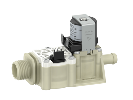
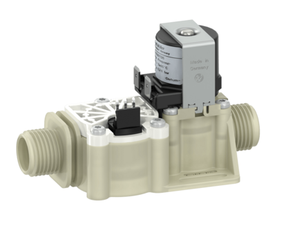
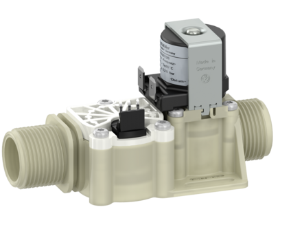
Flow meter turbine, with shut-off device

The combination of a flow meter and a solenoid valve in one compact unit enables, with suitable electronics, the accurate metering of a liquid together with the ability to interrupt the flow.

A servo controlled valve avoids water hammer when connected to the mains supply.

This unit can be used for measuring, feedback control or dosing as it ensures accurate measurement of liquid volumes. The simple internal pulse transmitter offers a long life time without risk of failure.

To avoid air entry causing inaccurate measurements, the flow meter is sited upstream from the solenoid valve.

The flow meter's output are pulses, where the frequency or the number of pulses are equivalent to flow rate or volume.
Depending of the orifice used different measuring ranges can be achieved.

Control and Regulating Valves, Flow Sensors, Metrology 17.007 2/2-way servo-controlled NC (normally closed, only valve) volume/flow rate determination 10 bar 12 l/min

Applications

  • liquid dosing
  • volume recording
  • laboratory equipment
  • dispensing equipment
  • Washing machines

Characteristics

  • Flow meters turbine:
  • high accuracy
  • different measuring ranges configurable
  • shut off via downstream solenoid valve
  • Valve:
  • Servo-controlled
  • Normally closed (NC)
  • solenoid replaceable while medium circuit remains untouched, solenoid coil snaps into place
  • Optimized water hammer characteristic by low noise emission according to EN 60730

Options

17007126
Material Inlet Outlet Length Height Depth ID
Ø A A1 Ø B B1 L H T
PA 66 G 1/2 15,5 nozzle 10,5 20 112,5 64 45 76900
PA 66 G 1/2 15,5 G 1/2 15,5 108 64 45 76901
PA 66 G 3/4 21 G 3/4 16,5 114,5 64 45 76902
PA 66 G 3/4 21 G 1/2 15,5 113,5 64 45 on request
PA 66 G 3/4 21 nozzle 10,5 20 118 64 45
PA 66 G 1/2 15,5 G 3/4 16,5 109 64 45
Other connector variants on request.
17007115
Material Inlet Outlet Length Height Depth ID
Ø A A1 Ø B L H T
PA 66 G 1/2 15,5 6 John Guest 96 64 46 76950
PA 66 G 3/4 21 6 John Guest 101,5 64 46 on request
Other connector variants on request.
orifices Ø mm constant pulses / l  *) metering accuracy Q min l/min Q max l/min p-Operating bar
7 94 ±3,0% 6,3 29 0,2 - 8
on request 5 262 ±3,0% 4,4 25,3 0,2 - 8
*) The constant (pulses/litre) are approximated values and may differ depending on installation and medium. It is recommended to evaluate the pulses/l within the actual installation more accurately.
Orifices sizes can be customized on request.

Technical data

  • Type flow meter turbine with shut-off device
  • Construction single chamber straight valve
  • Ways 2/2-way
  • mode of operation servo-controlled
  • Function volume/flow rate determination
  •   NC (normally closed, only valve)
  • Fitting position solenoid pointing upwards, for best results the flow meter should always be filled with liquid
  • Media Cold and heated potable water and physically and chemically similar media
  • T-Medium 5 - 60 °C
  • T-Ambient 5 - 60 °C
  • DN Valve 7 mm
  • Pressure range 0,2 - 10 bar
  • Flow factor Kv 12 l/min @ 1 bar
  • Flow regulator on request
  • Pressure surge according to EN 60730
  • Valve -
  • Coil type MS 26
  • Nominal voltage 220-240 V AC 50-60 Hz
  •   110 V AC 50 Hz
  •   12 V AC 50/60 Hz
  •   110 - 127 V AC 60 Hz
  • Nominal Power 9,6 W
  • Nominal voltage 24 V DC
  •   12 V DC
  •   other voltages on request
  • Voltage tolerance +10% -15%
  • Duty cycle 100%
  • Nominal power 6,5 W 7,5 VA (AC only)
  • Protection type IP 00
  • Coil connections Flat Tabs 6,3 x 0,8 mm according to EN 60529 (IP 00)
  • Insulation class H according to EN 60730
  • Flow meter turbine -
  • Flow rate 30,0 l/min max.
  • Nominal voltage 4,5 - 24 V DC
  • Current consumption 5 -13 mA
  • Signal connection open collector NPN
  • Signal voltage 0 V GND
  • Signal square-wave output
  • Duty factor of pulse 50% +/-5%
  • Signal load 20 mA max.
  • Leakage current 10 µA max.
  • Connections PANCON MAS-CON 156 MLSS (3 x AMP 2,8 x 0,58 mm)

Materials

  • Valve body PA 6/6, glass fibre reinforced
  •   PPE on request
  • Plunger Guide Stainless steel
  • Plunger and spring stainless steel
  • Membrane and sealings EPDM
  •   NBR (on request)
  •   VMQ (on request)
  • Coil coating PBT, PET or epoxy resin
  • Filter (in inlet) Stainless steel
  • Flow meter cover PBT
  • Slide bearing pin 1.4305 (18/8)
  •   1.4571 on request
  • O-ring EPDM
  •   MVQ on request
  •   FKM on request
  • Turbine PVDF
  • Magnet SrFeO
Technical inquiry
Technical inquiry

A. u. K. Müller GmbH & Co. KG

Dresdener Straße 162
D - 40595 Düsseldorf 

Telefon: +49 211 73 91-0
Telefax: +49 211 73 91-281

E-Mail: info(at)akmueller.de


A.K. Muller (UK) Ltd.
Unit 4, Brookside Business Park
Brookside Avenue, Rustington
GB - West Sussex BN16 3LP

Tel: +44 1903 788 888
Fax:+44 1903 785 817

E-Mail: valves(at)akmuller.co.uk


A.K. Müller France
10 Avenue du Gué Langlois
Z.A.E du Gué Langlois
F-77600  Bussy Saint Martin

Telefon: +33 1 64 62 95 14
Telefax: +33 1 64 62 95 12

E-Mail: info(at)akmuller.fr


A. u. K. Müller Shanghai
Rm26D, Huadu Mansion,
Zhangyang Rd. 838,
Shanghai, 200122, China

Telefon: +86 21 58 20 40 80
Telefax:  +86 21 58 20 42 12

E-Mail: info(at)akmueller.de


©2024 Copyright A. u. K. Müller GmbH & Co. KG